Polarization by Reflection
Plane of Incidence and Polarizations
When light hits a surface, some is reflected, and some is refracted (transmitted). The amplitude of the reflected and transmitted waves depends on the direction of the electric field. The direction is given with respect of the plane containing the direction of the plane containing the incident, reflected, and transmitted waves. The plane is called the plane of incidence.
If the electric field is perpendicular to the plane, the electric field is  polarized or transverse electric. If the direction of the electric field is in the plane of incidence, the direction of the magnetic field will be perpendicular to the plane. The magnetic field is said to be
  polarized or traverse magnetic.
Brewster’s Angle
The polarization of the reflected light depends on the angle of incidence. Brewster’s angle is the specific angle of incidence at which the reflected light is perfectly polarized perpendicular to the plane of incidence (the plane containing the incidence and reflected rays).
When the light is incident at the polarization angle (Brewster’s angle), the component with polarization parallel to the plane is completely refracted, while the component with polarization perpendicular to the plane is partially reflected and partially reflected.
A bit more detail
When light strikes a surface, the molecules on the surface can interact with electric field of the light. The molecules are more responsive to electric field that oscillate in a certain direction relative to the surface. When light with a certain polarization direction, typically parallel, hits the surface at a specific angle (Brewster’s angle for instance), the oscillating electric field can induce electrons in the surface molecules to move in that direction.
The movement of electrons absorb some of the light energy, reducing the intensity of the reflected light in that particular polarization. As a result, the parallel component of the electric field is largely absorbed or suppressed.
On a molecular level, electrons in the material respond to the oscillating electric field of the light. When the electric field is aligned in a way that drives electrons parallel to the surface, it increases interactions between the field and the molecules, leading to energy absorption. The absorbed energy is often transformed into heat within the material or reradiated in other directions, rather than being reflected.
(1) 
Double Diffraction and Birefringent
Optical isotropy vs. Anisotropy:
- Optically isotropic materials:These are materials, such as liquids, glasses, and crystals with cubic symmetry that have the same optical properties in all direction. The speed of light and refractive index are independent of direction and polarization in theses materials
- Optically anisotropic materials:** Certain crystals, lick calcite, are anisotropic, meaning their optical properties vary with direction. These materials can be split into two distinct polarized components traveling at different speeds.
When unpolarized light enters a birefringent material like calcite, it splits into two rays: the ordinary ray (o-ray) and the extraordinary ray (e-ray). The phenomenon is called double refraction or birefringence.
The ordinary ray obeys snell’s law, behaving as if a crystal with a refractive index of  . The extraordinary ray (e-ray) does not obey Snell’s law in the usual way; its speed and refractive index (
 ) depend on the direction of propagation within the crystal relative to the crystal’s optic axis.
The two rays e-ray and o-ray are linearly polarized with perpendicular polarizations
Phase difference
Consider the case where incident light enters a birefringent material in the shape of a cube with thickness  . Before reaching the cube, the light propagates through a medium with a refractive index
  and wavelength
  . Upon entering the cube, the light splits into two components: the ordinary ray and the extraordinary ray, each experiencing a different refractive index due to the birefringent properties of the material. These distinct refractive indices cause the two rays to travel at different speeds within the cube, resulting in a phase difference between them.
The phase difference between the two rays is equal to
(2) 
The equation/derivation is shown below. Recall that e and o rays are linearly polarized electric fields, so each of them can be represented as
(3) 
(4) 
where  and
and  are wavenumbers. Because both waves leave the cube at the same time, time
  does not influence the phase difference between two rays, and we only need to consider , , and
  .
.
The phase difference between two rays is equal to to the number of cycle difference between the two electric field, and the number of cycle traveled by each ray is equal to  and
and  . One complete cycle is equal to
  radians, converting the difference into radians, we get
  and
and  .
.
Using refractive index,  and
and  can be rewritten as:
(5) 
giving us:
(6) 
In Phase
- When
 , the two rays are in phase after traveling a distance across the birefringent material, so rays before the polarization is same as rays after polarization.
Half Wave Plate
- When
 , the maximum of a ray corresponds to the minimum of the other ray.
Quarter Wave Plate
- When
 , resultant waves form a circular polarization.
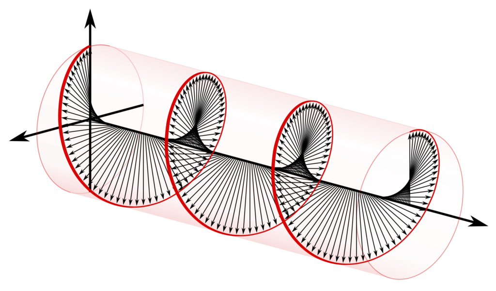
Circular Polarization
Circular polarization occurs when the two orthogonal (linearly polarized) electric field components are of equal magnitude and are out of phase by  , or one quarter wavelength. There are two types of circular polarization:
Similar to unpolarized light, when circularly polarized light passes through a polarizing sheet, its intensity is reduced by half. Therefore, a polarizing sheet alone cannot be used to distinguish between unpolarized and circularly polarized light.
- Right-handed/counterclockwise circularly polarized light
- left-handed/counterclockwise circularly polarized light
To make this distinction, an additional quarter-wave plate can be added after the circularly polarized light. The quarter-wave plate introduces an extra phase shift, which either adds to or subtracts from the original  phase difference, resulting in a total phase difference of
  or
or  . This converts the circularly polarized light into linearly polarized light, where the electric field oscillates along a fixed direction. The result polarization direction is at
  to the optic axis of the quarter-wave plates by the law of superposition.
We can demonstrate this linear polarization by passing the light through a polarizing sheet and rotating the sheet until its axis makes an angle of with the optic axis of the quarter-wave plate. At this angle, the intensity will drop to zero, confirming the presence of linear polarization and distinguishing it from unpolarized light.
Polarization by Scattering
When unpolarized light (light with electric fields oscillation in all directions) strike an atom in gas, it induces oscillations in the electrons within that atom. These oscillations act like tiny dipole antennas that re-emit light in various directions.
The direction of oscillation of theses electrons determines the direction of the re-emitted light’s electric field, which affects the observed polarization.
Consider the figure above, where an unpolarized light wave with electric field components propagating along the axis strikes atoms at point  . The incident electric field causes electrons in these atoms to oscillate in directions perpendicular to the incoming wave, specifically along the
  and
and  axes.
axes.
An observer positioned at  long the -axis will see only the oscillations along the -axis. This is because an oscillating dipole does not radiate along its own axis, meaning the observer at cannot detect oscillations along the -axis. As a result, the light observed at is linearly polarized along the -axis.
As the observer moves away from the -axis and toward the -axis, oscillations along the -axis become increasingly visible, weakening the polarization effect. Observers positioned along the -axis (looking in the forward or backward direction) can see oscillations in both the – and -axes, resulting in scattered light that is unpolarized.